
When you first start to diagnose a new model of transmission, you can sometimes be overwhelmed with all of the information you need to learn. A CVT transmission is no different, all you need to understand is the different inputs to the computer and the way the transmission works.
In this issue we’ll look at the 2010 Nissan Murano with a RE0F09B. The transmission is built by Jatco and is also referred to as the JF010E. A common complaint is sluggish while taking off from a stop when hot but worked right when cold, which is what this vehicle was doing.
An added bit of information is that this particular vehicle had been to the dealer numerous times, resulting in having installed two remanufactured transmissions. These instances are particularly tricky since it’s unlikely that the problem is actually in the transmission. Not taking any chances we’ll go through a thorough diagnosis.
Initial Checkout
The first thing you should do when one of these vehicles arrives in the shop is check for codes in all modules and road test the car. The shop ran into their first problem when they found low battery voltage and a charging systems problem. It’s easy to skip this diagnostic check if the car starts and works okay for the most part. But many shifting and other problems can be caused by something as simple as low battery voltage. Not with just this vehicle but many other vehicles as well. The minimum battery voltage you’d expect to see after a vehicle has sat overnight is 12.45V. We could do an entire article on this point but let’s continue.
There were a few codes about low power, lost communication and a range switch. The codes were in the body control module, anti-lock brakes, total integrated power model, tire pressure monitoring system and transmission control module. The battery could defiantly have something to do with problem considering the codes appeared in more than one module.
Replacing the battery took care of all the codes except the P0705, range switch circuit. After clearing the codes it only reappeared in the transmission control module. So far so good.
Everything appeared okay during a visual inspection of the wires, connector pins and the range switch. The range switch also checked out on the dash and the scan tool with each range reading correctly. This never changed whether the car was acting up or not.
When it “acted up” the engine would not exceed 3,000 rpm or pick up speed, no matter what you did with the throttle.
Data PID Movies
Here’s an instance where being able to capture a movie and transfer it to your computer comes in handy. With a printout of the movie when it worked right and during the malfunction it makes it a lot easier to notice errors and problems.
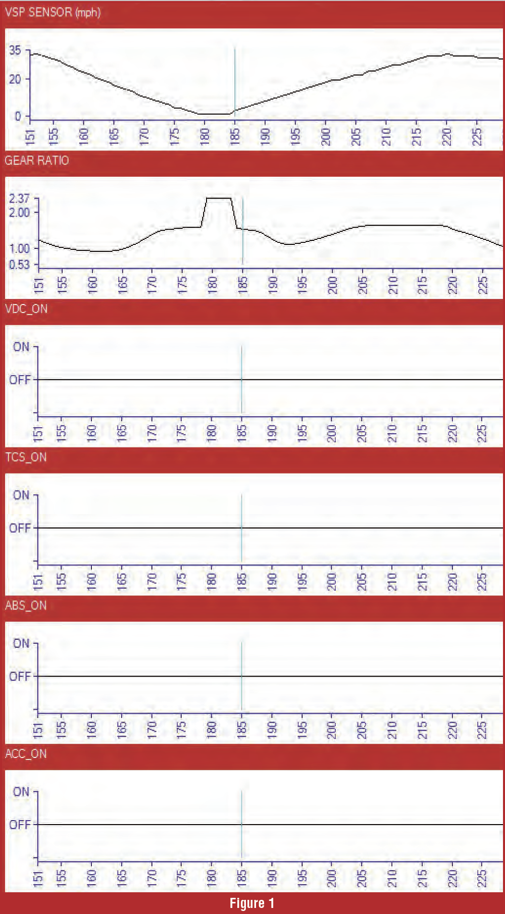
Some of the main systems like BCM (Body Control Module), VCD (Variable Displacement Compressor), TCS (Traction Control System), ABS (Anti-Lock Brake System) and ACC warning systems all have PIDs on scan tools that you can check that read on or off (figure 1). Both recorded movies looked the same. None of the PIDs changed in any of these systems so we’ll just set this aside, for now. At this point we’ll try to establish whether the problem is engine or transmission related so we’ll do a few more basic checks.
Checking line pressure on a CVT is similar to any other transmission except they can reach close to 1,000 psi. It’s a bad idea to use a mechanical pressure gauge in this instance since you run the risk of a hose rupture with the gauge inside the car. A better way is to use a pressure transducer and then read the pressure from your scan tool or volt meter.
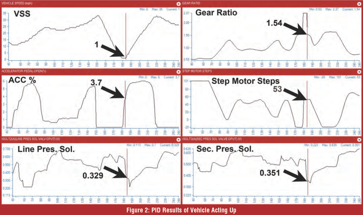
Figure 2 shows the results when the vehicle acted up. We have selected a few PIDs to help check pressure and compare the transmission operation when it was working well and when it had no power. We selected the VSS (Vehicle Speed Sensor) to keep track of speed. We monitored the gear ratio and stepper motor to watch the ratio change and how the stepper motor was working. Then the pressure PIDs, ISOLT 2 (line pressure) and ISOLT 3 (secondary pressure).
If you look at the two pressure PIDs you’ll see them mirror each other. On some models you may have desired pressure PIDs that match. This model did not have the desired PIDs.

Using Figure 3 to compare, we’ll duplicate the same driving conditions when just taking off from a start. The VSS jumped to 1 MPH and the Accelerator pedal percent is close to the same in both movies.
Now let’s look at the line pressure solenoid and secondary pressure solenoid amperage. They are also the same in both movies. At this point we’ll consider the results acceptable. Part of diagnosing is ruling out what is working right and narrowing down other possibilities. There’s a lot that’s working right on this car and it’s leaving us with just a few more possibilities.
Comparing figures 2 and 3 there’s something that stands out: The stepper motor recorded 53 steps in figure 2 while only showing 8 steps in figure 3. This might lead you to believe it’s inside the unit but remember, the dealer replaced it, twice.
Notice too, that along with the stepper motor difference it also shows a ratio difference in our figures 2 and 3 graphs. The ratio difference would explain the lack-of-power complaint and also lead us to think it might be a command problem.

The computer doesn’t try to calculate the ratio while stopped because there isn’t a speed sensor signal. Once the vehicle starts moving and calculating the ratio, you can see the ratio quickly change on the graph, so it feels like it’s taking off in 2nd or 3rd gear. This explains lack-of-power sensation.
Let’s take a closer look at the graph when acting up (Figure 4). This zoomed in section of the graph is just looking at the gear ratio and step motor steps PIDs during take-off.
Look at how far the gear ratio PID changed the ratio when the vehicle starts to move. The step motor steps should be around 10 when taking off from a stop and this graph is showing it is at 50. This shows that the computer is commanding the wrong number of steps, to the stepper motor.

The CVT Control System
Now our challenge is to figure out why the TCM is telling the transmission to be in the wrong ratio. We’ll look at the inputs to the TCM (Figure 5).
List of Inputs:
- Range Switch
- Accelerator Pedal Position Switch
- Closed Throttle Switch
- Engine Speed Sensors
- Cvt Fluid Temp
- Overdrive Control Switch
- Stop Lamp Switch
- Primary and Secondary Speed sensor
- Primary and Secondary
- Pressure Switch
- TCM powers
We can include the steering angle and “G” sensors even though they go through the ABS. Here’s an example of where various modules share data. It is known that the “G” sensor will cause transmission ratio change issues. The factory manual doesn’t include it in their diagnostic information but we’ve seen cases where it’s caused transmission malfunctions.
We looked in all of the systems for PID data that looked strange and compared it to a movie of a good working transmission and couldn’t come up with a cause for this complaint.
After a thorough diagnostic we concluded that the problem was actually in the TCM. It’s not the direction we like to go, but our diagnostics ruled out everything the TCM uses to control the transmission and we also knew it had good power and ground.
Replacing the TCM fixed the problem; the car drove perfectly. Now, you might be thinking, “Why didn’t we replace the TCM first instead of wasting all that time?” Sure, we may have fixed this one quicker by simply replacing the TCM, but it’s more common that a simple issue or failed sensor is the cause of the problem. Not to mention, if you work at developing your diagnostic skills you can get really good at it and get through these tests pretty quickly, unlike the dealer that replaced the transmission twice without any success.
And what made this diagnostic exercise much easier was having the proper equipment; a scan tool that would record a movie and the software to upload it to a PC.
CVT’s are becoming mainstream today, with practically every auto manufacturer using them. Parts are becoming readily available and they’re pretty easy to work on.
If you’re new to working on CVTs then have some fun with the next one that comes in for a service. Check the functionality of your scan tool and become familiar with the systems data. If you get familiar with it you never know, maybe the dealer will be sending you work.
A special Thanks to Ron and Mike from Silverdale Transmission Inc. in Silverdale Washington for the information they shared on this little jewel.
Click here to Visit Original Post by Jarad Warren